A Philips 850A. What was once a beautiful stately radio device is now no more than a wreck. What could we make of this radio?

The chassis, which is supplied separately, is a composition in rust.

The underside after years of standing still under bad conditions.

The engine tuning. What once made this device special is now a jammed old mess.

The chassis has been given a different end tube. It was a war tube.

Free expression has run its course here.

The power supply. Could this radio set play again?

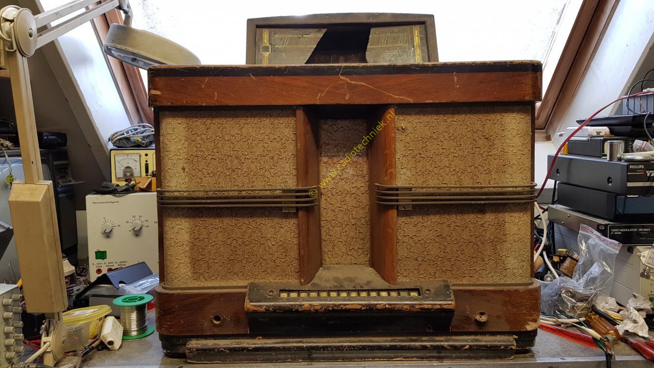
The cabinet looks like a lot, but a terrible spectacle is coming.

The speaker cloth of this radio was original. No one on the auction site had seen that. For me this was the reason to buy this beautiful radio device.

Part of the cabinet under the mechanical memory of the motor tuning was knocked away with an axe.

Here you can clearly see how part of the cabinet was knocked away with an axe.

The keyboard is completely bulged by the moisture. Inside, the wood was cracked and broken.

Another terrible drama. There should be 5 bars on both loudspeaker grilles. the bottom of both sides is missing.

The inside of the keyboard. The keyboard is completely warped.

The keyboard clearly shows how the wood has broken loose.

Here you can clearly see how one corner has been knocked out of the cabinet. Replacing the bottom plate is the only option.

The bottom plate consists of two parts, the lower part is good and usable. The second part is plywood. This part has been worked with the ax but has also been completely under water. Where the layers of the plywood had come loose. And the whole of misery fell apart.

Carefully remove the footboard.

Here the loose layers of the plywood.

Removed the keyboard.

The pieces of the keyboard, the two large parts, were one whole.

The rusty nails that came out of the radio cabinet. With a lot of effort.

Removed the bottom plate.

The cabinet bare. Bottom plate removed.

Re-gluing the keyboard.

New and repaired parts fit in the cabinet.

A view of the bottom of the radio cabinet.

Assembling the keyboard and measuring the push buttons.

The top view of the keyboard.

Glue the bottom into the cabinet.

The cabinet with bottom.

Gluing the keyboard into the cabinet.

Here you can see that the keyboard will straighten itself in the cabinet.

Cabinet with sound wings and keyboard.

Repairing the speaker grille.

Here bending a brass rod.

The speaker grill viewed from above.

Here's an idea of the end result.

The speaker grille.

The inside of the speaker grille finished and riveted.

Both speaker grilles repaired.

The copper work is ready to go back on the cabinet.

The parts of the engine tuning.

Tuning capacitor wheel.

The parts cleaned and ready for assembly.

The slip clutch is a whole again.

Drive of the motor tuning.

Fully assembled and completely new.

The engine up close. Everything about this piece of mechanics is back together.

A new chassis from the production line. Also a new push button unit. And a new power transformer. And on the right the new motor drive. Beautiful, isn't that production of the year 1938.

The buttons unit from the keyboard.

New components placed loosely on the chassis.

Restoration of intermediate frequency band filters.

The chassis with the new components.

Everything that needed to be riveted to the chassis has been done.

The construction of the electronics can begin.

We use original wire for the wiring.

Wiring the chassis.

It must also be wired at the top of the chassis.

Of course we use new tar capacitors.

The wiring is mounted on the chassis again.

Building the subframe with a high-frequency receiver coil and band switch.

A separate test of a high-frequency circuit.

Here is the loose setup.

The tuning capacitor and the first high-frequency circuit are fixed on the chassis.

The construction of the low-frequency part.

The second IF circuit mounted on the chassis.

The rebuild continues slowly.

Intermediate frequency circuit detector test.

Measured at the output of the detector. Input is first grille IF tube.

Installed the first bandwidth switch and mechanical part.

Tuning indicator EM1 installed and tested.

Low-frequency part done.

All tubes are on the chassis.

The revision of the first intermediate frequency band filter.

A stray neighborhood frog coming to help me.

Look the neighborhood cat strung the beads.

Mid-frequency bandpass filter ready with lampshade.

The chassis looks beautiful. Completely late 1930s but new.

The construction of the high-frequency part the second high-frequency stage is placed.

The shielding shots between the high-frequency stages are also very important.

The oscillator section completely overhauled.

Testen van de ocillator

The chassis is already starting to become quite complete.

The top also looks like a Philips 850A.

Tuning the oscillator.

The coil buses together on the left, the two high-frequency stages on the right, the oscillator section.

To place the shift rod for the wave range switching, the oscillator coil had to be removed from the chassis.

Component placement is just very precise.

The chassis had to be removed from the repair stand. Otherwise, the switching rod for the wave range switching could not be placed.

The cassis back in the repair stand.

Here you can see how tight it fits. The shift rod of the waveband switching just passes the ceramic capacitor.

Meanwhile, the drive mechanism of the engine tuning has also been installed. And the chassis is equipped with new tubes. Unfortunately not the EM1 which has been made unaffordable by handy Harry.

The chassis with a few new buttons. And the coupling between the drive and the mechanical memory of the motor tuning.

Here's the coupling up close. Nice piece of technology that makes the radio so special.

The chassis is now complete. Here's a picture of the component side.

This video shows the operation of the engine tuning. Unfortunately, medium wave stations cannot be received well here. At the time of making the movie.

Here's a photo of the back. All the details are there like rivets.

The front side of the chassis.

The next problem is the dial hood. The dial pointer is projected as a light image on the dial. This makes the setting of the dial pointer very precise.

What do you need for that. A new dail cap, of course.

You also need a mirror, mirror on the wall who is the nicely's of us all?

A dail with working lighting.

A way to move the dial pointer from left to right and vice versa.

And here begins the adjustment of the dial pointer relative to the dial.

And this is the light image.

The shape of the lamp is very important here.

The reflector is also very important, a lot of rust just doesn't work.

And a good mirror, mirror on the .....

Then you get this light image over the entire dial from left to right and vice versa.


And then the surprise.....

A new cabinet for a Philips 850A.

Or is this the same cabinet? That's impossible.

This cabinet is truly beautiful. The shine the deep drawing in the veneer.

And yes this is the same cabinet. There are people who can restore this so beautifully. And unfortunately I am not. But whoever did this cabinet is an insane craftsman.

And such a speaker grille looks great on such a cabinet.

Because there is a new bottom in the cabinet, the chassis must be measured again in the cabinet.

And that is not easy, the press studs must run smoothly and must not get stuck.

Placing the chassis took me a lot of time.

But finally the chassis is in place and the feet under the chassis have marked the place in the bottom shelf of the cabinet.

Here is a picture of the keyboard and its position in the cabinet.

Nice isn't it chassis in a new cabinet.

You can somewhat recognize a radio in the front.

Placing the cloth. The cloth has not become new but is still original.

And here you can see how the loudspeaker is mounted in relation to the cabinet and the sound wings.

Now it has already become a radio. Only the press studs left. And both lampshades.

The speaker cloth is back in the cabinet. Time to do the rest.

The speaker back in it's place.

Here you can see the part of the cabinet that was knocked away with an axe.

And here's the bottom plate back on. the two small pieces are still missing.

And so the smallest details have to be restored.

Because you want the keyboard to look like new again.

Unfortunately, a piece of the aft bulkhead is missing. But we are still looking for a solution for that.

The cabinet is like new again.

And with the picture we started with, we also end. Everything can be restored. Often it is a matter of time, money and patience.

This video is an encore. How does an 850A play on a local AM station in this case ExtrAM. This radio is new and this was the first cabinet test with its own loudspeaker.